Here is a good article for researchers who deal with Solar Cells in the Simulink environment.
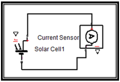
A common situation that solar cell researchers face is they typically design electrical power systems (e.g RLC Circuits) with blocks from the SimPowerSystems library, and then would like to connect the ‘Solar cell’ block to this circuitry (see figure 1).

Figure 1 – Circuitry designed in SimPowerSystems domain, and User wants to replace DC Voltage Source with a Solar Cell block.
However, as intuitive as figure 1 may seem to be, this method is not possible. This is because the ‘solar cell’ block is obtained from another library and is considered as a member of the family of another domain (SimElectronics). Therefore, when the researcher tries to connect this block to the circuitry, he’ll find that Simulink does not allow the connection.
The tip
Here’s the tip on how to connect the ‘Solar Cell’ block to a circuitry designed with SimPowerSystems. Listed below are the steps in sequence, where each of it is assisted by a diagram.
-
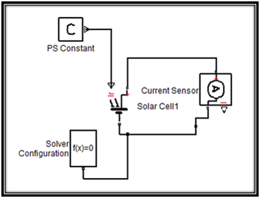
Connect a current sensor block (Simscape>Foundation Library>Electrical>Electrical Sensors) to the ‘Solar Cell’ block. This block measures the current and outputs a physical signal which will be fed to the SimPowerSystems domain later.
-
Connect a ‘PS Constant’ block (Simscape>Foundation Library>Physical Signals>Sources) to specify the irradiance value (Light Intensity in W/m2) that falls onto the Solar Cell. Plug in the Solver Configuration block (Simscape>Utilities) to specify the solver parameters that is needed by the model for simulation.
-
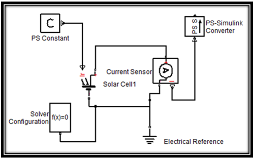
Connect an Electrical reference block (Simscape>Foundation Library>Electrical>Electrical Elements) to represent electrical grounding for the circuit.

-
Connect a ‘PS-Simulink Converter’ block (Simscape>Utilities) to convert the physical signal to a Simulink signal.
-
Finally, connect a ‘Controlled Current Source’ block from the SimPowerSystems library (SimPowerSystems/Electrical Sources) to convert the Simulink input Signal to an equivalent current signal in SimPowerSystems.

With this final step, the connection between the Solar Cell and SimPowerSystems has actually been established. The circuit with the solar cell can then be interfaced with the SimPowerSystem circuit as shown in figure 2.

Figure 2 – Connection between Solar Cell and Circuits in SimPowerSystems
Conclusion
That’s the tip to interface the Solar Cell block to the SimPowerSystem domain. Hopefully you will find it useful in your research and development. Happy Working!
——————
Edit:
Wow, the amount of question here baffles me!
If you still intend to post questions, please have a look at: Questions?


thanks a lot. I got output and I am very happy. my name is Rajendran from India. sraj_4u@rediffmail.com
LikeLike
I am happy to find this because it help me to understand lot of things.
Please Allow me to ask you a question; I have a problem in my simultaion; I did a model for photovaltaic panel and an other model for cuk converter and I want connect these tow models; but my problem is that the time of simulation of this tow models is not the same; when photovoltaic”s time is ‘1S discret’ and cuk converter model’s time is ‘0.04s continuous’. so When I simulat this it give me a wrong resuts; although when I did each one alone I fine right resuts
LikeLike
Hi Meryem,
Could you send me your model so I can take a look a it? I’d like to know how you interface the two models of different simulation solvers because that may be the source of the problem.
LikeLike
Hi Matlabideas,
Please help me, i can’t get simulation. The problem was in Solver Configuration block. How can fix it ? Could i get parameter for given example. Great thanks in advence. Can you contact me aungaung184@gmail.com
LikeLike
What kind of error are you getting? Can you share a link to your model?
LikeLike
Hello. Thank you for the site. I need a solar cell in a power system. The current after the PS S is the real current of the system ? I need a controled current source ? And, how can I change the irradiance ? Is it possible insert a function ?
LikeLike
Hi Alex,
Not sure if I understand your question. The physical model represents a graphic representation of a system which you can interface with more “conventional” Simulink blocks via the interface blocks provided. Beyond the underlying formulae that determines the cell voltage, the Solar cell block behaves like a Voltage Source block.
If you need to change the irradiance, you should use a Simulink source block. Connect that block to the Solar cell via a Simulink-PS Converter and you’re good to go. 😉
LikeLike
Thank you!
LikeLike
Good morning ! Mr. matlabideas ! I have an error while simulation this error is shown in the following. Please help me !
(Nonlinear solver: Linear Algebra error. Failed to solve using iteration matrix. Initial conditions solve failed to converge. Dependency found among topology equations. Check for missing reference node. )
LikeLike
Send me the model that causes that error, and I’ll help you take a look. My email: matlabideas@gmail.com
LikeLike
Hi,
I tried the above method of configuration. I connect a resistor to the output of the Controlled Current Source, and I realised the Controlled Current Source gives a fix output current. Is there anything I have missed out in the solar cell configuration?
Thank you.
LikeLike
Sir,my simulation of circuit works without error.however though I am setting the parameters like Short-circuit current 2 A and open circuit voltage as 17 V the output of solar cell block, The voltage and current parameters measurements after PS-Simulink Converter do not match as per input.
I need your help in above.looking for your positive response..
LikeLike
how to use with variable inductor?
LikeLike
what are the parameter of solver configuration? my simulation dont run says:
Steady state solve failed to converge.
…Nonlinear solver to advance time one step failed to converge due to Linear Algebra error. Failed to solve using iteration matrix.
……The model may not give enough information to make it possible to solve for values of some of its variables. Specific advice is given below.
Tie variable ‘untitled1.Subsystem_OUT1.v’ to a definite value, for example by connecting an appropriate domain reference block.
Dependency found among topology equations. Check for missing reference node.
LikeLike
thanks . its useful i hope to be in touch with you to finalize my master about PV system connected to grid. please send me any useful posts concerned that.
LikeLike
mann you are a saviour!!
LikeLike